PSMP

Individual Pitch Control Head

PSIVH series

Every attach is driven by its own linear motor. One head covers equal-pitch, irregular and random layouts.

0.1 ㎛Position resolution
±0.003 mmRepeatability
1,000 mm/sMaximum speed
3 GMax. acceleration
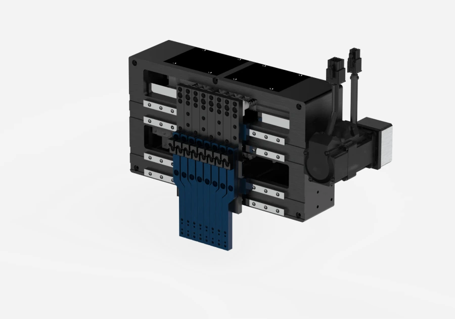
Product render of the individual pitch control head, in a 4-axis example configuration: four attach bars hang from the black body at unequal spacings.

Pitch control

Pitch conversion resets the spacing of parts picked from a tray to the spacing the process needs. It works in two ways, and this product is the individual type.

Equal variable type

Every attach moves together at the same spacing. Suited to repetitive equal-pitch conversion.
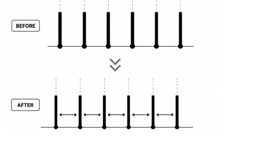
Equal variable type diagram: six attaches at even spacing before conversion open out to a wider spacing after conversion, still evenly spaced.

Individual pitch controlThis product

Each attach moves on its own, which supports asymmetric layouts and per-attach position compensation.

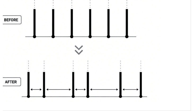
Individual pitch control diagram: six evenly spaced attaches each move to a different spacing after conversion.

Key features

Independent axis control
Each attach is controlled on its own, so one head handles equal-pitch, irregular and random layouts.
Compact direct drive
Linear motors sit inside the head, removing ball screws, belts and external drives.
High-speed individual motion
Each attach runs independently at up to 3 G and 1,000 mm/s.
Absolute position feedback
High-resolution absolute encoders report position in real time, so the head runs without homing.
Vision-based 0.1 µm compensation
Each attach position is compensated in 0.1 µm increments from vision feedback.
Low maintenance
With no cams, linkages or belts there is little wear or backlash, so accuracy holds over time.

Inside the head

Cut-away render of the head interior: the interface PCB across the top, two rows of red and blue magnet arrays above and below, four attach blocks travelling between them, and the linear guides at each end.
  • Magnet Array
  • UVW Linear Motor Coil
  • Optical Absolute Encoder
  • Encoder Scale with Protective Cover
  • Interface PCB
  • Linear Guide
  • Attach Block
  • High-Flex Cable

Applications

The individual pitch control head mounted in equipment, lowering its four nozzles over a wafer stage.
Diagram: a 4x4 tray grid on the left becomes a row of six evenly spaced attaches after the arrow

Tray-to-process pitch conversion

Converts tray pitch to the pitch the process needs.
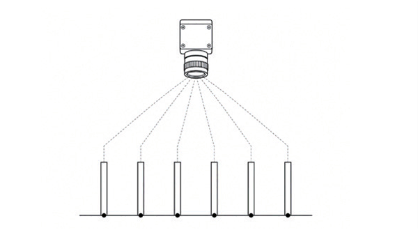
Diagram: a vision camera views several attaches below it and measures the position offset of each

Vision offset compensation

Compensates each attach position from vision feedback.
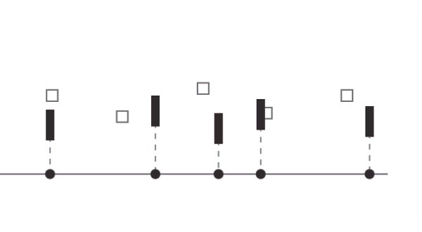
Diagram: five attaches at unequal spacings, each aligned to a scattered square component position

Asymmetric layout support

Turns an irregular tray layout into the layout the process needs.

Specifications

Specifications change with the configuration. · The figures below are a 4-axis example

Part numbering

  1. PSIVHSeries
  2. Number of attach
    • 02 : 2 Para
    • 04 : 4 Para
    • further options are available
  3. Maximum travel pitch
    • 100 : 100 mm
    • 300 : 300 mm
    • further options are available
  4. Payload per attach
    • 300 : 300 g
    • 500 : 500 g
    • further options are available
Individual Pitch Control Head technical specifications
SeriesPSIVH
Motor typeLinear motor · direct drive
Position repeatability±0.003 mm
Position resolution0.1 ㎛
Maximum speed1,000 mm/s
Maximum acceleration3 G
Supply voltage24 / 48 Vdc
Power per attach24 Vdc · 1 A
Power (rated / peak)6.12 / 10.7 W
Force (rated / peak)12.2 / 21.4 N
Current (rated / peak)0.8 / 1.4 Arms
Force constant15.28 N/Arms
Number of phases3
Magnet pitch14.1 mm
EncoderOptical, absolute
Output signalBiss-C
Sensor voltage5 Vdc
Number of axes4
Maximum travel pitch270 mm
Payload per attach700 g
Dimensions318 (W) x 38 (D) x 170 (H) mm
Total massApprox. 4 kg
Mounting4-M5 TAP DP8 · Ø5 / Ø4 locating pins
ConnectorMolex 105310-1216 x 4 (mates with 105308-1216)

※ Based on a pitch range of 15-60 mm.

Dimensions & options

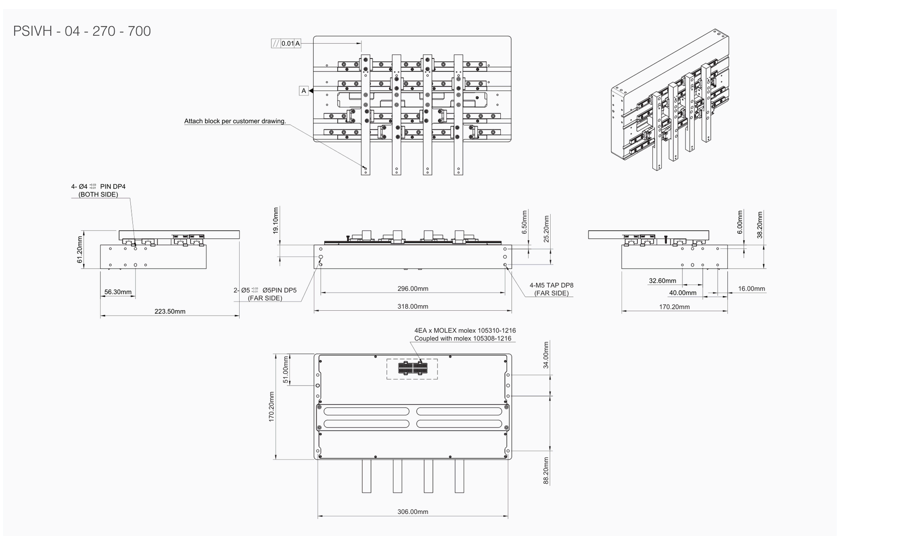
Outline drawing of a 4-axis example configuration: plan, front, side and rear views showing the overall 318 mm width, 170.20 mm height and 38.20 mm depth, the 4-M5 mounting taps and the Molex connector position. The PSIVH-04-270-700 marking on the drawing is the part number of that example configuration.
Before design sign-off

The attach block is made to the customer drawing. Confirm installation conditions with the approved drawing.

Options

Diagram: red arrows pointing at the head body from above, below, left and right

4-side mounting

Mountable from all four sides, in any orientation.

Diagram: a Molex cable plugging into the connector on the back of the head

Molex quick connection

Molex connectors make cable connection and wiring quick.
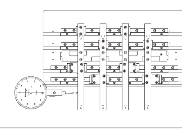
Diagram: a dial indicator probe touching an attach bar to measure straightness

Precision attach alignment

Aligned with a dial indicator to within 0.01 mm straightness.

Download

Complete the request form and privacy consent to download a file.

Source: product leaflet

Product range

Contact

PSMP · Pick & Place Solutions

Contact →
Download resources